ODM DZ47LE Series Residual Current Operated Circuit Breaker Supplier, Factory
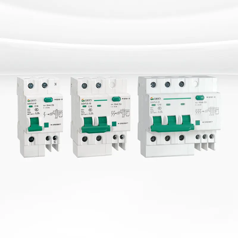
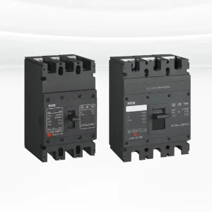
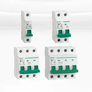
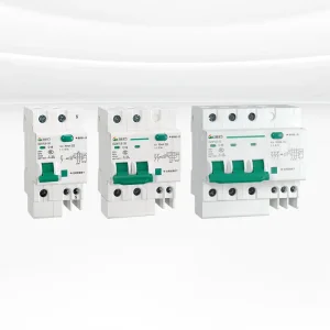
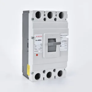
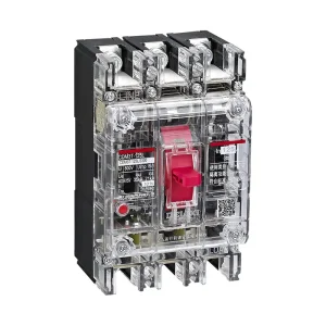
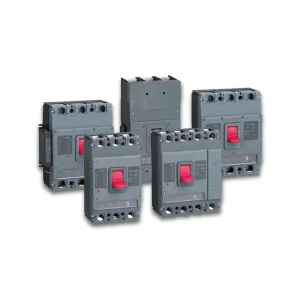
The DZ47LE series leakage circuit breaker is an electrical device with many excellent features, which are manifested in its advanced structural design, stable and reliable performance, strong breaking capacity, and beautiful and compact appearance. The housing and main components of this series of products are carefully manufactured with impact-resistant and highly flame-retardant materials to ensure safety and durability in various environments.
The DZ47LE series leakage circuit breaker is suitable for AC 50Hz or 60Hz power systems, with a rated working voltage of up to 400V and a rated current range from 6A to 63A. It is widely used in overload, short circuit and leakage protection of lighting, distribution lines and equipment in office buildings, residential buildings and similar buildings. In addition, under normal circumstances, the product can also be used as a conversion device for infrequent line switching, providing a flexible power management solution.
It is worth mentioning that the DZ47LE series leakage circuit breaker not only complies with the GB16917.1 standard, but also has passed the CCC certification, which fully demonstrates its superiority in safety and reliability. This makes the product very popular in the market and an ideal choice for users in the field of electrical protection.
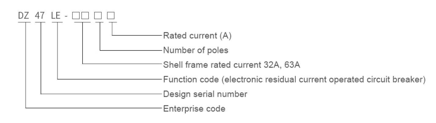
Model meaning
Product features
Project / Model
DZ47LE-/1N
DZ47LE-/2
DZ47LE-/3
DZ47LE-/3N
DZ47LE-/4
Number of pole wires
Unipolar two wire
Unipolar two wire
Three poles and three wires
Three pole four wire
Four pole four wire
Rated voltage Un(V)
230
230/400
Shell Grade Current (32A)
6, 10, 20, 25, 32
Shell Frame Grade Current (63A)
6, 10, 20, 25, 32, 40, 50, 63
Rated leakage current IΔn(A)
0.03, 0.05
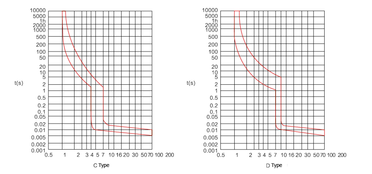
According to the characteristics of the instantaneous tripper
C Type (5-10) In, D Type (10-14) In
Rated voltage Un(V)
Single pole two wire, two poles 230V; Three pole, three pole four wire, four pole 400V
Rated short-circuit capability Icu(A)
4500 (6000)
Rated residual on-off and breaking capacity IΔm(A)
2000
Rated residual inactive current IΔno
0.5IΔn
1. The breaking time of residual current action is shown in the table below:
IΔ(A)
IΔn(A)
Break time (s) when residual current equals the following values
IΔn
2IΔn
5IΔn
5A, 10A, 20A, 50A, 100A, 200A, 500A
IΔtb
6~63
0.03, 0.05, 0.1, 0.3
0.1
0.05
0.04
0.04
0.04
Note:
a. The tests for 5A, 20A, 50A, 100A, 200A, and 500A are only conducted during the verification action, and no tests are conducted on current values greater than the lower limit of the instantaneous tripping range of overcurrent.
b. Conduct the test at the current value where IΔt is equal to the lower limit of the instantaneous tipping range for overcurrent of type C or type D.
2. The overcurrent protection characteristics are shown in Table 2:
Serial Number
Rated current In(A)
Initial state
Test current
Set time t
Expected results
Notes
1
6~63
Cold state
1.13In
t ≥ 1h
No tripping
2
6~63
Following the previous experiment
1.45In
t < 1h
Tripping
The current steadily rises to the specified value within 5 seconds
3
6~63
Cold state
2.55ln
1s < t < 60s
Tripping
In ≤ 32A
1s < t < 120s
Tripping
In > 32A
4
6~63
Cold state
5In
t ≥ 0.1s
No tripping
C Type / D Type
10In
t < 0.1s
Tripping
10In
t ≥ 0.1s
No tripping
16In
t < 0.1s
Tripping
3. Mechanical and electrical life:
Electrical life: 2000 times, COS φ = 0.85~0.9;
Mechanical life: 2000 times;
Operating frequency: In ≤ 25A (240 times/h), In > 25A (120 times/h);
4. Insulation impulse voltage resistance:
The poles are connected together and can withstand a peak impulse voltage of 6000V between the neutral poles;
The poles are connected to the neutral pole and can withstand a peak impulse voltage of 8000V between the metal brackets.
5. Surge voltage resilience:
The residual current action circuit breaker has the ability to withstand the surge overvoltage under the action of the peak current of 200A inrush current and the peak voltage of 2.52Un, and does not cause malfunction.
6. Tripper characteristic curve:
7. Wiring specifications: The torque of the wiring screw should not be less than 1.5N·m.
8. Ambient air temperature requirements:
The maximum temperature of the surrounding air is +40°C, the minimum is not less than -5°C, and the average of 24 hours does not exceed +35°C. The influence of the ambient air temperature on the circuit breaker is detailed below:
Temperature (°C)
-15
-15
0
10
10
30
40
55
Correction factor for rated current
1.19
1.19
1.13
1.06
1.06
1
0.96
0.89
9. Selection of copper wires for installation:
Rated current In(A)
Nominal copper conductor cross-sectional area (mm²)
10 and below
1.5
10~20
2.5
20~25
4
25~32
6
32~50
10
50~60
16
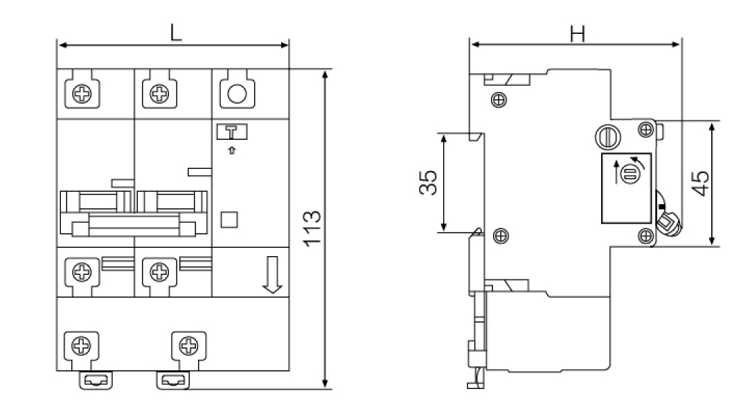
Shape and installation dimensions
Number of poles
L(mm)
H(mm)
Inm=32
Inm=63
1P+N
45
54
74
2P
63
72
77.8
3P
90
103.5
77.8
3P+N
99
117
77.8
4P
117
135
77.8
Frequently Asked Questions (FAQ)
QWhat is the primary application of the DZ47LE series leakage circuit breaker?
It is designed for overload, short circuit, and residual current (leakage) protection in lighting, distribution lines, and power systems. It is extensively applied in residential, commercial, and office buildings.
QWhat electrical standards does this circuit breaker comply with?
The DZ47LE series is fully compliant with the GB16917.1 standard and has successfully passed China's CCC certification, ensuring safe and reliable operations.
QWhat is the electrical and mechanical lifespan of the DZ47LE series?
It features a mechanical durability of up to 2,000 operations and an electrical service life of up to 2,000 operations under standard power factor conditions (COS φ = 0.85 to 0.9).
QHow does ambient temperature affect the current performance of the breaker?
The base operational parameters are calibrated at 30°C. If temperatures fluctuate, a correction factor is applied. For example, at -15°C, the factor is 1.19, while at high temperatures like 55°C, the correction factor drops to 0.89.
QWhat is the recommended installation wire and screw torque?
Copper wire sizes must match the rated current, starting from 1.5 mm² for 10A and below, up to 16 mm² for 50-60A. The installation wiring screw must be tightened with a torque of no less than 1.5 N·m.