
1 / 4
| Product Name | Electric Current | Number of Poles | Operation and Maintenance Methods | Operating Handle Type | Special Types |
|---|---|---|---|---|---|
| HR3 | 200 | 3 | 1 | BX | Z |
| ↓ | ↓ | ↓ | ↓ | ↓ | |
|
200: 200A 400: 400A ... |
3: 3P |
1: Front side lever transmission mechanism 2: Front central lever transmission mechanism, rear maintenance 3: Side operating handle 4: No panel front side transmission mechanism, rear maintenance |
BX: Rotary operating mechanism Default: Ordinary handle |
Z: Left operation Default: Right operation |
| Product Name | Current | Number of Poles | Combination Type of Fuse and Auxiliary Switch |
|---|---|---|---|
| HR6 | 160 | 3 | 0 |
| ↓ | ↓ | ↓ | |
|
125: 125A 160: 160A 250: 250A ... 630: 630A 800: 800A |
3: 3P |
0: With fuse, without auxiliary switch 1: With fuse and auxiliary switch |
| Product Name | Current | Number of Poles | Auxiliary Switch Type |
|---|---|---|---|
| HR5 | 160 | 3 | 1 |
| ↓ | ↓ | ↓ | |
|
160: 160A 400: 400A ... |
3: 3P |
0: Without blown fuse signal device (fuse link with blown fuse indicator) 1: With blown fuse signal device (fuse link with blown fuse striker) |
| Product Name | Current | Number of Poles | Operation and Maintenance Methods | Operating Handle Type | Special Types |
|---|---|---|---|---|---|
| HR3 | 200 | 3 | 1 | BX | Z |
| ↓ | ↓ | ↓ | ↓ | ↓ | |
|
200: 200A 400: 400A ... |
3: 3P |
1: Front side lever transmission mechanism 2: Front central lever transmission mechanism, rear maintenance 3: Side operating handle 4: No panel front side transmission mechanism, rear maintenance |
BX: Rotary operating mechanism Default: Normal handle |
Z: Left operation Default: Right Operation |
| Model | HR6 | HR5 | HR3 | |||
|---|---|---|---|---|---|---|
| Use Category | AC-22B | AC-23B | AC-22B | AC-22B | AC23-B | AC-21B / AC-22B |
| Current Specification (A) | 160, 250, 400, 630, 800 | 125, 200, 315, 400, 630 | 125 | 160, 250, 400, 630 | 100, 200, 315, 400 | 200, 400, 600 |
| Voltage (V) | 380 | 660 | 800 | 380 | 660 | 380 |
| Certification Standards | GB/T 14048.3 IEC 60947-3 | |||||
| Certification | CCC | |||||
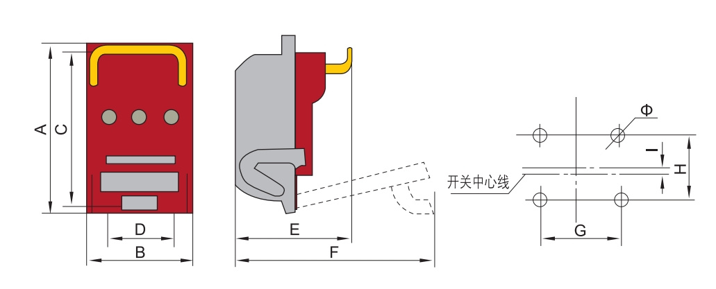
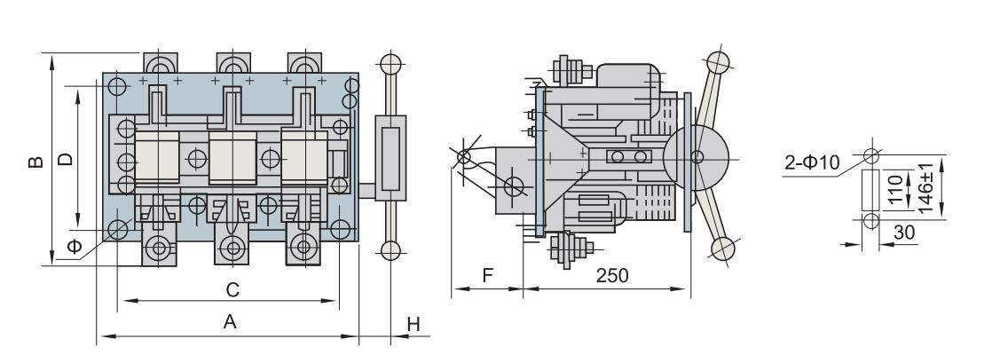
| Specification | 125/160 | 200 | 400 | 630/800 |
|---|---|---|---|---|
| A | 215 | 280 | 300 | 300 |
| B | 138 | 189 | 248 | 248 |
| C | 200 | 260 | 280 | 280 |
| D | 80 | 120 | 160 | 160 |
| E | 145 | 165 | 195 | 195 |
| F | 260 | 360 | 378 | 373 |
| G | 80 | 120 | 160 | 160 |
| H | 40 | 60 | 60 | 60 |
| I | 2.25 | 2 | 3.5 | 3.5 |
| Φ | 8-6.5 | 8-8.5 | 8-8.5 | 8-8.5 |
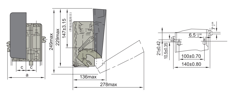
| Specification | 160/31 | 160/30 |
|---|---|---|
| a | 167 | 160 |
| c | 40 | 40 |
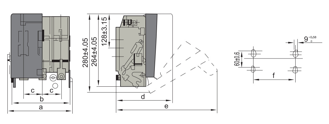
| Specification | 250/31 | 250/30 | 400/31 | 400/30 | 600/31 | 600/30 |
|---|---|---|---|---|---|---|
| a | 227 | - | 250 | - | 296 | - |
| b | - | 210 | - | 233 | - | 280 |
| c | 62 | 62 | 70 | 70 | 85 | 85 |
| d | 197 | 197 | 213 | 213 | 228 | 228 |
| e | 347 | 347 | 363 | 363 | 378 | 378 |
| f | 130 | 130 | 130 | 130 | 200 | 200 |
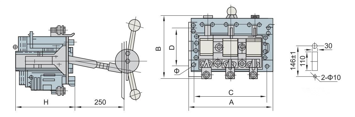
| Specification | 200 | 400 | 600 |
|---|---|---|---|
| A | 275 | 295 | 325 |
| B | 205 | 225 | 265 |
| C | 230 | 250 | 280 |
| D | 130 | 130 | 130 |
| H | 183 | 184 | 203 |
| Φ | 7 | 7 | 7 |
| Specification | 200 | 400 | 600 |
|---|---|---|---|
| A | 275 | 295 | 325 |
| B | 205 | 225 | 265 |
| C | 230 | 250 | 280 |
| D | 170 | 170 | 170 |
| F: | 87 | 87 | 104 |
| H | 53 | 53 | 43 |
| Φ | 7 | 7 | 7 |